The existing panel has been scrapped and I have modified the panel to reduce the clutter and keep it simple. The base frame of the panel is a 3 layer of carbon fiber with removable aluminum panels on the front side. If instrument layout is required to be changed later it will be a easier modification to complete. I still plan on installing a center section and a small side panel on the lower port and starboard of the main panel. I am using a MGL E1 engine monitoring instrument which will monitor 4 CHT's, RPM, Oil temperature, and Oil pressure and Voltage. The unit has the ability to trigger two alarm lamps that will alert the pilot if anything goes out of pilot specified limits.
I fabricated new tubing for rudder pedals and made up new nylon support blocks which attach to the upper side of the Canard wing (floor). Eyeball fittings have been used on the firewall for cable pass through and all surplus holes have been closed.
Below I am using a Vernier cable to control my T-Tail trim system, this will allow fine tuning or large changes of the trim. The vernier connects to a idler arm which in turn connects to the two cables (in sheaths) going to the aft t-tail wings. I have the vernier cable encased in a aluminum tube which keeps the cable from flexing and is absolutely necessary. The vernier cable is secured to the idler arm using two (2) B-Nuts locked down tight for double security. A brand new mixture cable was installed, replacing the original spliced unit. Accident investigator mentioned that this cable should not have been spliced as it is a major control item. I had a welder investigate the sleeve and silver solder method used to splice and he explained it was bound to fail. The stainless inside metal rod should have been welded with stainless if anything,
Below is my linkage to the T-Tail trim wings on the port sidewall. I did not want to have any chance of failure of the linkage to the T-Tail. The closeup shows my addition of two extra B-nuts to the vernier cable going forward which eliminates any chance of the center B-nut coming loose and slipping.
The circumference of the removable tail cone edges were found to be just raw foam, so I dug out the foam to 1/2 inch and replaced the edges with cabosil/epoxy for a extremely hard edge.
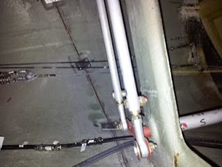
Below is the lower end of drive arms showing the adjustable rod ends enabling fine tuning adjustments.
Photo below is looking upward just aft of the baggage compartment space. At the top there are two drive arms for the ailerons.


